008613968780263

Leave Your Message
-
CONTACT NUMBER
-
 CONTACT NUMBER
-
 CONTACT

A Shielding Frame can look like a simple metal border, yet a narrow seam may weaken the protection around sensitive electronics. Choosing one means matching the frame to the enclosure, operating frequency, and installation conditions—not merely choosing a material. Small gaps matter. So does pressure at the joint.
MarketsandMarkets estimated the global electromagnetic interference (EMI) shielding market at USD 7.8 billion in 2023, forecasting USD 9.8 billion by 2028. This broad market estimate covers more than shielding frames, so it should not be treated as a frame-specific demand figure. Still, it signals why careful component selection matters as electronic devices become more compact. EMC engineer Henry W. Ott’s guiding principle captures the value of planning: “The best way to solve EMC problems is to prevent them from occurring in the first place.”
In practice, compare frame geometry, conductivity, corrosion resistance, and contact consistency. Check whether the design accommodates the actual gasket, coating, fasteners, and enclosure tolerances. A frame that performs well in a drawing may behave differently after assembly. That detail is easy to overlook. Ask suppliers for relevant test methods and performance data, then verify the complete assembly under realistic conditions. No single material or shape suits every application. The right choice balances shielding performance, durability, manufacturability, and cost—and leaves room to revise assumptions when test results disagree.
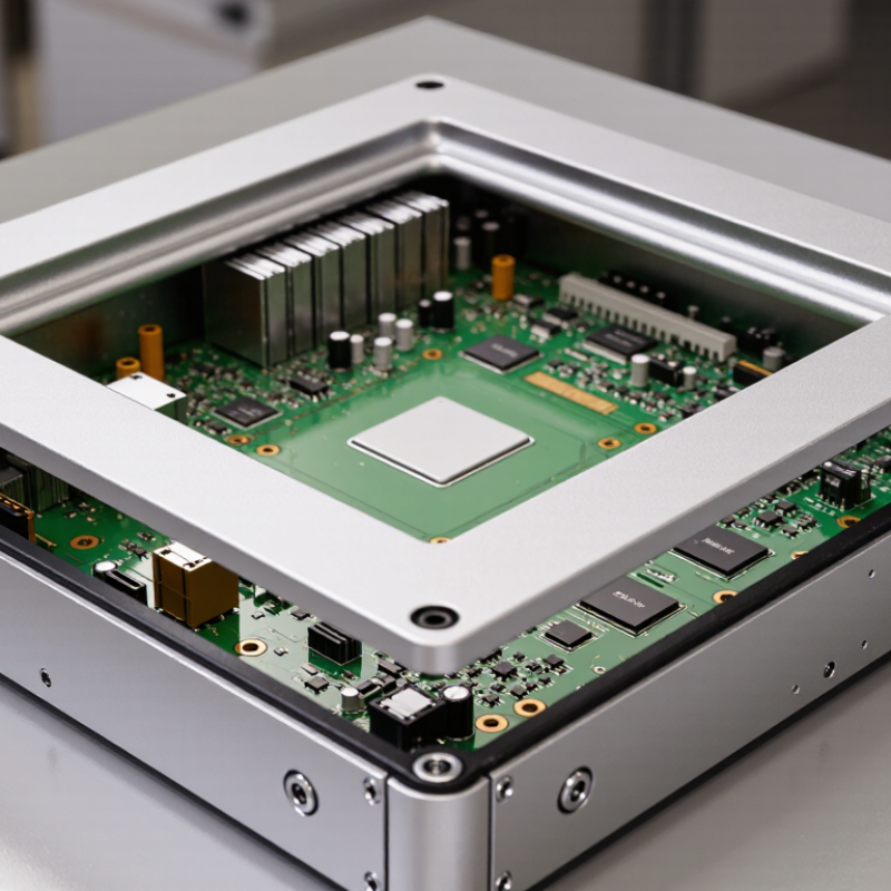
A shielding frame is not simply a metal border. Its purpose is to control electromagnetic interference around a specific opening, such as a display, access panel, or ventilation area. Define the threat first: identify the frequency range, likely noise sources, required shielding effectiveness, and whether the frame must also provide grounding, airflow, or frequent access. A frame that performs well on a bench can disappoint after installation. Tiny gaps, paint on contact surfaces, and uneven fastener pressure can create leakage paths.
Material and geometry should follow those requirements. Conductive gaskets need steady compression; corners and joints need reliable electrical contact. Measure the opening, including its tolerances, and check how the frame meets the enclosure. Grand View Research estimated the global electromagnetic shielding market at USD 7.46 billion in 2023, with projected growth through 2030. That figure signals broad demand, not a performance guarantee for any particular frame. Test the assembled enclosure under relevant conditions. IEEE Std 299 describes methods for measuring shielding effectiveness of enclosures. Real installations can still differ. A rushed prototype may hide weak contact at one corner. That is worth checking twice.
| Selection Dimension | What to Determine | Practical Selection Guidance | Verification Check |
|---|---|---|---|
| Purpose and location | Identify whether the frame supports an EMI/RFI shield, bonds a removable panel, or surrounds an opening in an enclosure. | Choose a frame geometry that maintains a continuous conductive path around the opening and fits the panel or enclosure design. | Review the assembly drawing and confirm how the frame connects to adjacent conductive parts. |
| Shielding frequency range | Determine the frequencies of concern and the required shielding effectiveness for the complete assembly. | Do not select by frame material alone. Gaps, seams, apertures, coatings, and contact pressure can affect system-level shielding. | Assess the finished enclosure using the applicable test method and acceptance criteria. |
| Material and conductivity | Consider electrical conductivity, corrosion resistance, strength, weight, and compatibility with mating materials. | Use a conductive material and surface finish suited to the environment and the required electrical bond. Avoid assuming that a conductive-looking coating provides a reliable contact. | Check material specifications, finish details, and contact resistance or bonding requirements. |
| Bonding and contact | Establish how the frame will make electrical contact with the enclosure, panel, gasket, or fasteners. | Provide clean, consistent contact surfaces and a suitable fastening pattern. Paint, oxide, or contamination at a contact interface may increase impedance. | Inspect the contact path and verify continuity across the assembled joint. |
| Dimensions and tolerances | Specify opening size, frame width, flatness, thickness, mounting-hole locations, and allowable manufacturing variation. | Account for panel movement and tolerance stack-up so the frame seats evenly without creating unintended gaps. | Compare the frame and mating-part drawings, then check fit on a representative assembly. |
| Gasket and compression | If a conductive gasket is used, identify its cross-section, compression range, and installation method. | Design the frame and closure to provide uniform compression within the gasket supplier’s specified range; avoid over-compression or uneven loading. | Confirm compression around the perimeter and inspect for continuous contact. |
| Mechanical loads | Determine fastening loads, vibration, shock, repeated opening, and any load carried by the frame. | Select adequate stiffness and mounting support so the frame does not distort, loosen, or lose contact during service. | Review structural requirements and test the assembly under the relevant operating conditions. |
| Environment and sealing | Identify exposure to moisture, dust, temperature changes, chemicals, and outdoor conditions. | Choose compatible materials and finishes. If environmental sealing is required, treat it as a separate design requirement from electromagnetic shielding. | Verify the required environmental protection level with the completed assembly and applicable test procedure. |
| Installation and maintenance | Consider access for assembly, inspection, cleaning, gasket replacement, and service-panel removal. | Use a frame design that can be installed consistently and reassembled without damaging contact surfaces or shielding components. | Perform a service trial and document installation and inspection steps. |
| Compliance and validation | Identify applicable product, industry, and customer requirements before finalizing the design. | Define measurable acceptance criteria for the assembled product; a frame by itself does not establish compliance. | Validate the complete enclosure or product against the specified requirements and test methods. |