008613968780263

Leave Your Message
-
CONTACT NUMBER
-
 CONTACT NUMBER
-
 CONTACT

Choosing the right Micro Connectors for global sourcing starts with the real application, not a supplier’s catalog image. A connector that fits a prototype may fail after repeated mating, vibration, heat, or moisture exposure. I have seen teams focus on contact count and unit price, then overlook cable bend radius and locking strength. Small details matter. Define signal type, rated current, voltage, pitch, dimensions, mating cycles, and operating temperature before requesting quotes. Confirm whether the connector must handle power, high-speed data, or both. Ask for drawings, material declarations, test reports, and traceable samples. A polished datasheet is useful, but physical evidence is stronger.
Global sourcing adds another layer of judgment. Compare tooling ownership, minimum order quantities, lead times, packaging, quality controls, and engineering support. Check plating thickness, contact material, insulation grade, and tolerance control. These features often decide whether production remains stable. Request first-article samples from more than one qualified supplier, then test them under realistic conditions. Measure insertion force, electrical resistance, retention, and temperature rise. Document every result. Do not rely on a low quote alone. It may exclude inspection, custom tooling, or replacement stock. Supplier audits and independent verification can reduce avoidable surprises, although they cannot remove every risk. No checklist is perfect. Requirements may change after field testing. That is not failure; it is useful evidence. A careful sourcing process balances technical performance, supply continuity, ethical manufacturing, and total cost. The best choice is rarely the smallest or cheapest connector. It is the one that performs reliably, receives global support, and remains practical during full production.
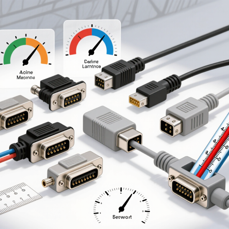
Choosing a micro connector for global sourcing starts with a precise electrical definition. Pitch is the distance between contact centers, often measured in millimeters. A 0.4 mm pitch saves board space but leaves less room for assembly tolerance. Measure the mating footprint, not only the drawing. Small errors become expensive.
Current and voltage define contact construction and insulation needs. Record normal current, peak current, and duty cycle for each circuit. A connector rated for 0.5 A continuously may fail when motors create short surges. Check voltage clearance, creepage, and temperature rise at the actual pitch. Derating is wise in hot enclosures. I once focused on nominal current and overlooked startup load. That was a useful mistake.
Signal speed requires more than a headline frequency. Review impedance, crosstalk, insertion loss, return paths, and shielding. For a 5 Gbps differential link, test the connector with the cable and board stackup. Ask suppliers for mating-cycle data, dimensional inspection records, and samples from consistent production lots. Confirm tolerances in writing. A sample can pass while volume production drifts. I still prefer a second validation build, although schedules resist it. Keep a clear requirement sheet with pitch, current, voltage, speed, temperature, and acceptance limits. Suppliers can quote faster when the questions are concrete.
| Connector Application | Typical Pitch | Typical Current per Contact | Typical Voltage Rating | Typical Signal Capability | Best-Fit Use Cases | Key Sourcing Checks |
|---|---|---|---|---|---|---|
| Board-to-Board Micro Connector | 0.35–1.00 mm | 0.3–1.5 A | 30–100 V DC | Up to approximately 10–25 Gbit/s per differential lane, depending on geometry, mating height, routing, and signal-integrity design | Compact control boards, portable electronics, sensor modules, and mezzanine assemblies | Check mating height, stack-up tolerance, contact resistance, retention force, coplanarity, and differential-pair impedance performance |
| Micro Wire-to-Board Connector | 0.80–2.00 mm | 1–3 A | 30–250 V DC | Low-speed control, power, sensor, and moderate-speed digital signals; high-speed performance depends on shielding and contact layout | Internal harnesses, displays, battery leads, fans, sensors, and compact embedded systems | Verify wire gauge range, crimp pull force, locking method, polarization, cable bend radius, and terminal availability |
| FFC/FPC Connector | 0.30–1.00 mm | 0.2–1.0 A per contact | 30–100 V DC | Up to approximately 5–10 Gbit/s for suitable differential layouts and short interconnects | Displays, cameras, touch panels, compact consumer devices, and folding or space-constrained assemblies | Confirm cable thickness, exposed-contact direction, bottom or top contact orientation, locking mechanism, bend life, and insertion depth |
| Micro Coaxial Connector | Approximately 1.00–2.00 mm mating interface | Usually below 0.5 A | 30–60 V DC | Commonly suitable for RF and high-speed links from several GHz to tens of GHz, subject to cable, termination, and controlled impedance | Antennas, wireless modules, GNSS, cellular communication, test equipment, and high-frequency sensor systems | Check characteristic impedance, frequency range, insertion loss, return loss, shielding, cable routing, and mating-cycle requirements |
| Micro Circular Connector | Contact spacing commonly 1.00–2.50 mm | 1–5 A per contact | 30–300 V DC | Typically low-speed power, control, and sensor signals; shielded versions can support selected high-speed interfaces | Industrial sensors, robotics, medical instruments, lighting, and compact external interfaces | Evaluate ingress protection, keying, shell material, cable sealing, vibration resistance, locking style, and mating cycles |
| Micro USB-Type Power/Data Interface | Contact pitch commonly about 0.65–0.80 mm | Typically up to 1.5–3 A, depending on the interface specification and implementation | Usually 5–20 V DC, depending on the negotiated power mode | USB 2.0 supports up to 480 Mbit/s; newer reversible interfaces can support substantially higher rates when the complete system is designed for them | External charging, service ports, peripherals, development equipment, and compact consumer products | Confirm protocol generation, power-delivery requirements, shell grounding, plug durability, EMI performance, and connector orientation |
| Micro Board-Edge Connector | 0.50–1.27 mm contact pitch | 0.5–2 A per contact | 30–100 V DC | From low-speed control to approximately 10–16 Gbit/s per lane in suitable high-speed designs | Replaceable modules, memory assemblies, expansion cards, and compact equipment interfaces | Check PCB thickness, edge plating, insertion force, retention, contact wipe length, polarization, and card-guide tolerance |
| Engineering note: The values above are representative selection ranges rather than universal ratings. Actual current, voltage, and signal-speed limits depend on contact spacing, conductor size, insulation system, temperature rise, derating, mating cycles, PCB layout, cable construction, shielding, and applicable safety requirements. Always validate the final design against the supplier's current datasheet, qualification report, and applicable regional compliance requirements. | ||||||
| Global Sourcing Dimension | Recommended Requirement | Why It Matters | Suggested Verification | Typical Risk | Acceptance Criteria | Documentation to Request |
| Pitch and Mechanical Fit | Define pitch, row count, mating height, outline, and keying before requesting quotations | Small dimensional differences can prevent mating or create assembly interference | Review 2D drawings, 3D models, tolerance stack-up, and first-article samples | Wrong mating part, insufficient clearance, or unreliable automated assembly | All mechanical dimensions remain within the approved tolerance range | Product drawing, CAD model, tolerance table, and inspection report |
| Current and Temperature | Specify continuous current, peak current, ambient temperature, and allowable temperature rise | Micro contacts have limited conductive area and can heat rapidly under load | Perform temperature-rise testing at the maximum rated load and worst-case ambient condition | Contact overheating, oxidation, resistance increase, or premature failure | Temperature rise and contact resistance meet the approved design limits | Current-rating curve, derating data, resistance limits, and test method |
| Voltage and Insulation | Specify working voltage, transient voltage, creepage, clearance, and insulation resistance | Voltage capability is affected by spacing, contamination, altitude, and insulation material | Check dielectric withstand, insulation resistance, and environmental derating | Arcing, leakage current, insulation breakdown, or safety nonconformance | Required dielectric and insulation values are achieved after environmental testing | Electrical ratings, safety test reports, material declarations, and compliance records |
| Signal Speed and Integrity | Define data rate, impedance, rise time, insertion loss, return loss, and crosstalk targets | Connector performance depends on the complete interconnect rather than pitch alone | Use TDR, eye-diagram, S-parameter, and protocol-compliance testing where applicable | Bit errors, signal reflection, electromagnetic interference, or unstable links | Measured eye margin and impedance remain within the system specification | High-speed test reports, S-parameter files, impedance data, and application guidelines |
| Environmental Reliability | Define operating temperature, humidity, vibration, shock, corrosion, and mating-cycle targets | Environmental exposure can change contact resistance and mechanical retention | Review thermal cycling, damp heat, vibration, salt-mist, and durability test results as applicable | Intermittent connections, fretting corrosion, seal failure, or loss of retention | Electrical and mechanical performance remain within limits after qualification testing | Qualification plan, reliability report, material specifications, and change-control policy |
| Manufacturing and Supply Continuity | Specify terminal plating, applicable materials, packaging, traceability, and approved alternatives | Stable production requires consistent materials, tooling, and process control | Audit process capability, inspect incoming samples, and confirm lot traceability | Plating variation, mixed revisions, counterfeit risk, or unexpected lead-time changes | Consistent quality across approved production lots and documented engineering changes | Certificate of conformity, material declaration, PPAP or equivalent package, and PCN process |